


By Darren Court, Museum Director/Curator and the WSMR Public Affairs Office
Edited by Jenn Jett, Museum Specialist
The primary sources for information and photographs on the Hermes Program come from the White Sands Missile Range Museum’s Archives. Other resources used will be noted as appropriate and where applicable.


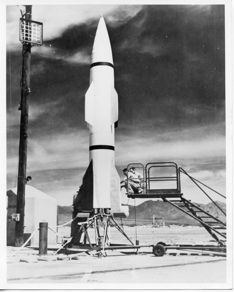


The Hermes Project
The Hermes program was the Army’s second missile program, started in November 1944 in response to the German V-2 program, with the purpose of determining the missile needs of the field forces. With General Electric as the prime contractor, the task was to “seek and develop long range missiles that could be used against both ground targets and high-altitude aircraft.” The Hermes Program had the following objectives:
1. Obtain experience in the handling and firing of large missiles.
2. Provide vehicles for experiments directly concerned with the design of future missiles.
3. Provide vehicles for operational tests of components for future missiles.
4. Obtain ballistics data for high-altitude trajectories by developing and proving various means for tracking and measuring trajectories.
5. Provide vehicles for upper atmosphere research projects.
The Hermes A-1, A-2, and A-3 series were part of the Hermes I program, which used the German “Wasserfall” configuration for its original design. Work on Hermes A-1 as an anti-aircraft missile began in 1946, but the scope of the entire Hermes Project changed in 1947, limiting it to a surface-to-surface missile. Six A-1 test vehicles were approved for guidance and control tests against surface targets; one of these was damaged beyond repair in static testing and the other five were flight tested between May 19, 1950 and April 26, 1951.
In addition to the “normal” V-2 tests, the Army undertook the development and testing of a longer-range cruise missile type weapon, this became the Hermes II – a high velocity ramjet-powered missile. The cruise missile itself, called the “comet,” was to be boosted by the V-2. However, this changed the dynamics of the rocket, requiring larger tail fins to be added. In addition, the V-2 was fitted with ramjet powered “wings” at the guidance and control section of the rocket.
Early research and development work under the Hermes Project consisted of general study, component development and experimental work at White Sands Proving Ground with modified German V-2 material. Numerous avenues and designs of test vehicles were pursued during the early start of the project. For instance, by the end of the year 1950 the Hermes Project had four test vehicles under development; the Bumper (a V-2 with WAC Corporal) for testing the feasibility of separation at high velocity of a two-stage missile; Hermes A-4 (V-2) missiles made from captured German rocket spare parts for high altitude research; Hermes B-1, which was a ramjet for tests and; Hermes II, a two-stage missile using the V-2 as its first stage rocket and a ramjet in the second stage.
Many of the contemporary records of the V-2 and Hermes Programs present information that is sometimes different or even completely contradictory with each other. Much of this confusion can be attributed to the steps that WSPG and the Army took to manage information that needed to remain classified while also communicating with the public about events that were unmistakable as the testing and launching of cutting edge technology. The most well-known instance of this type of redirection involved the launch of Missile 0, the first of the Hermes II model, which took off from Army Launch Area 1 (ALA-1) on 29 May 1947 and immediately began heading south instead of north, over the city of El Paso and the US-Mexico border before impacting just outside of downtown Cuidad Juarez. To hide the classified information on Project Hermes


The following are the types of missiles designed and tested for the Hermes Program:
| Model/Variant | Notes |
| RV-A-5 Hermes A-1 | First Launch 19 May 1950 |
| Hermes A-2 | Originally began in 1946, not pursued |
| RV-A-10 Hermes A-2 | Studies began in 1949 |
| Hermes A-3A | First Launch on 13 March 1953 |
| Hermes A-3B | First Launch on 11 May 1954 |
| Hermes B | Interim test vehicle, May 1947 |
| RTV-G-10 Hermes C-1 | Developed into the Redstone |
| RV-A-3 Hermes II | First Launch 29 May 1947, landed in Juarez, Mexico |
Research and development were conducted on missile structures, transonic and supersonic aerodynamics, remote and on-missile guidance and control, ground launching and handling equipment, flight test instrumentation, subsonic and supersonic ramjet engines, fuels and propellant combinations, and rocket engines of various types. The project was divided into three phases: literature search, familiarization with German guided missile development, and design and development of experimental systems.
The Hermes Program continued for 10 years. During that time, 103 missiles were fired, of which 67 were German V-2s. However, GE participation in the program was terminated by agreement on 30 June 1951.
RV-A-5 Hermes A-1
| Type: | Research test vehicle |
| Guidance: | Inertial/remote guidance |
| Propellant: | Liquid oxygen, alcohol |
| Range: | 75 miles (120km, intended) |
| Speed: | 1,800 miles per hour (2,900km/h) |
| Length: | 25.5 feet (7.77m) |
| Diameter: | 34.6 inches (87.8cm) |
| Weight: | 6,630 pounds (3,000kg) |
| First Launch: | 19 May 1950 |
In November 1944, the US Army Ordnance Department awarded a contract to the General Electric Company to develop a long-range guided missile for the United States Army. This effort was called Project Hermes. The GE contract covered the investigation, research, development, and engineering work leading to the design of a series of long-range missiles required by the Army. After a number of configurations had been studied, it was decided to base the program on the German “Wasserfall” prototype missile configuration.
In addition to the existing Project Hermes, the General Electric Company was assigned the task of firing a number of V-2 rockets, which were to be constructed from the ground up. Large quantities of components for the German V-2 missiles and supporting equipment had been captured in the European Theater of Operations in 1945. The captured materiel was shipped to Las Cruces in August 1945 for use at White Sands Proving Ground. With the assistance of military personnel and German specialists, GE had the first V-2 rocket ready for static firing on 15 March 1946. The first V-2 was launched on 16 April 1946.
According to Leo D. “Pappy” White, GE’s Project Hermes field test director at White Sands, the assembly and testing of the V-2 rockets proved invaluable to the development of the Hermes series and other missiles. However, there was no real comparison between the two systems. The V-2 was a workhorse used only for experimentation purposes. The Hermes A-1 was considerably smaller than the V-2.
| Hermes A-1 | V-2 | |
| Length: | 25.5 feet | 46 feet |
| Diameter: | 34.6 inches | 65 inches |
| Weight (empty): | 3,400 pounds | 8,818 pounds |
| Weight (loaded): | 6,630 pounds | 28,440 pounds |
Since guidance problems were of major interest in the A-1 development program, the designers adopted the German “Wasserfall” missile configuration. This step also allowed the Hermes Project to utilize the experience of the German guided missile personnel who had been assigned to the Hermes Project at the inception of the program. Hermes motor experiments promised better performance with safer fuels, so the “Wasserfall” propulsion system was not incorporated into the A-1 rocket. The missile was 25.5 feet in length and 34.5 inches in diameter; its control and stabilizing surfaces were four fixed wings and four controlled fins; its new liquid propellant power plant generated 16,000 pounds of thrust to give the vehicle a maximum velocity of 1,800 miles per hour. Guidance controls consisted of roll-and-pitch stabilization using gyroscopes plus ground-originated radar signals operating jet and air control vanes. The rocket was highly maneuverable and an ideal test vehicle for a control experimentation.
Ground guidance was essentially a single tracking radar and a computer with the missile carrying a combination beacon-transponder. A comprehensive set of electrical test equipment for Hermes A-1 was designed by General Electric. This equipment resulted from experience gained in V-2 and Bumper operations, which indicated that an electrical failure of one type or another were the causes of the most lost time in pre-firing checkout of the missile.
Discontinuation of Hermes A-1 as a tactical missile was ordered on 18 May 1950, the day before the first firing of the A-1 at White Sands Proving Ground. Although none of the A-1 missile flights were completely successful, the functional operability of the system was well demonstrated. A solid propellant motor system was selected and applicable portions of the A-1 guidance system were to be employed. A 1,500-pound payload was to be carried a 75 miles at maximum range.

Today one of the few pieces of the project which remains can be found at Launch Complex 33. The site, which contains the original Army Blockhouse and V-2 gantry, numerous concrete launch pads, and a Hermes A-1, was officially recognized by the State of New Mexico as a state historical monument in February 1983. The launch complex was designated as a National Historic Landmark two years later in 1985.


RV-A-10 Hermes A-2
Hermes A-2 originated in 1946 as a wingless version of the A-1, but the plan was not pursued. Studies in 1949, directed toward development of low-cost missile system, were labeled as A-2. A solid propellant motor system was selected and applicable portions of the A-1 guidance system were employed. A 1,500-pound payload was to be carried to a 75-mile range. Development on Hermes A-2 was confined to work on the propulsion system. The A-2 motor was test-fired at the Air Force Missile Test Center in Florida using the RV-A-10 (A-2) test vehicle. Four firings were conducted. A hybrid propulsion system was developed for this project. It used polyethylene plastic as the fuel and concentrated hydrogen peroxide as the oxidizer. These hybrid motors, generating 1,050 to 20,000 pounds of thrust, were static fired, but the hybrid work was terminated in 1953 due to the lack of application for this technology.
Hermes A-3A/B
| Model: | Hermes A3-A | Hermes A-3B | |
| Guidance: | Remote guidance | Inertial guidance | |
| Propellant: | Liquid oxygen, alcohol | Liquid oxygen, alcohol | |
| Warhead: | Atomic, 1,500 pounds (680kg) | Atomic, 3,000 pounds (1,360kg) | |
| Range: | 150 miles (240km) | 100 miles (160km) | |
| Length: | 29 feet (8.8m) | 33 feet (10m) | |
| Diameter: | 40 inches (1.0m) | 47 inches (1.2m) | |
| First Launch: | 13 March 1953 | 11 May 1954 |
The Hermes A-3 program was initiated to design a surface-to-surface missile system carrying a 1,000-pound warhead with a range of 150 miles and a 33% circular area probable of 200 feet. Instead of using a gyroscopic, inertial, or other onboard guidance system, the Hermes A-3 would be command guided from ground stations onto the target. To develop different capabilities, the A-3 was separated into the A-3A and A-3B.
The A-3A was divided into two models, the A-3AE1 and the A-3AE2. The A-3AE1 was of the original A-3A design and was selected for an initial production run of twelve missiles in November 1950. The subsequent model, the A-3AE2, was developed to carry a 1,500-pound atomic warhead.
The A-3A was cancelled as a tactical missile in 1951. The flight test program for the A-3A to test propulsion and guidance systems for use on the A-3B concluded in January 1954 after seven launches.
Once the Army issued a requirement for a surface-to-surface missile capable of carrying a 3,000-pound atomic warhead, Hermes Program designers resurrected the A-3A and submitted a hastily modified design that increased the missile’s thrust from 18,000-pounds to 22,000-pounds. The flight test program for the A-3B was formulated in early 1953 as a series of 28 firings. The first six missiles were to be test-fired in order to perfect an operating system; the second six missiles were destined for tests of accuracy; the remaining missiles would provide data on system performance under simulated filed conditions. In mid-1953, the number of A-3B missiles authorized for flight tests was reduced to six, but the original objectives for the first six missiles were retained to demonstrate the feasibility of the basic guidance system concept.
Trajectory and scheme of operations were the same for both missiles. Launch was vertical; the missile made a 1G turn four seconds after launch and then was guided by radio command along a straight line until radio cut-off. After cut-off, pitch programming controlled elevation; command guidance continued in azimuth until dynamic pressure became insufficient for control. When the missile crossed the elevation null axis, combined continuous-wave radar and Doppler information were used to compute the desired impact point. This information was stored in the missile as corrective data along with information on departure of the missile from a vacuum trajectory. Post reentry maneuvers to a maximum of 2G allowed corrective actions to be taken. When the vacuum trajectory was tangent to a line passing through the target, the missile was programmed on this straight line. The terminal phase of flight, therefore, was essentially independent of variations in flight time.
Range safety requirements had been discussed for several years prior to the A-3B test flights, and positive steps had been taken to ensure emergency cutoff capabilities worked in previous test series. Safety developments to the time of the A-3B series resulted in a cutoff receiver and antenna mounted on fin #3 of the missile.
Although system accuracy was not demonstrated and, therefore, some of the A-3B flights considered fully successful, the series did prove the system inherently capable of the predicted performance based on the actual hardware employed. The General Electric Company’s participation in the Hermes Project was terminated by an agreement on June 30, 1951. Hermes Project technical work not terminated in that agreement was ended on December 31, 1954.
Timeline of Hermes A-3A/B Launches
7 August 1952
Hermes A-3A #1
Destroyed by explosion and fire during static tests at Malta Test Station.
13 March 1953
Hermes A-3A #2
Turbopump failure caused explosion 23 seconds into flight.
13 June 1953
Hermes A-3A #3
Tail section construction was changed to minimize spurious burning noted in previous flight. Missile reached velocity of 3,350 feet per second at burnout.
13 August 1953
Hermes A-3A #4
Missile velocity of 4,150 feet per second at burnout recorded.
05 October 1953
Hermes A-3A #5
Excessive velocity was blamed for roll instability occurring at 161 seconds.
21 October 1953
Hermes A-3A #6
Missile operated as expected until 75 seconds after launch; failure of the 150-volt and 120-volt batteries resulted in loss of flight control from ground.
20 November 1953
Hermes A-3A #7
Functioned until about 20,000 feet before impact when a tail fin control malfunctioned and the missile spun out of its trajectory.
15 January 1954
Hermes A-3A #8
Loss of stable flight control 53 seconds after take-off.
11 May 1954
Hermes A-3B (XSSM-A-16) #1
Altitude 106,000 feet; range 48.2 nautical miles. All systems performed well except electrical loss of B+ power at 141 seconds.
20 July 1954
Hermes A-3B #3
Altitude 117,600 feet; range 59.7 nautical miles. Proportional guidance blocked by ground equipment testing.
26 August 1954
Hermes A-3B #2
Altitude 9,200 feet; range 8 nautical miles. Emergency cut-off by a guillotine device.
21 September 1954
Hermes A-3B #4
Altitude 118,00 feet; range 61.7 nautical miles. All systems worked as expected.
19 October 1954
Hermes A-3B #5
Altitude 118,200 feet; range 63.3 nautical miles. All systems worked as expected.
16 November 1954
Hermes A-3B #6
Altitude 113,000 feet; range 54.5 nautical miles. Range data erratic due to variations in beacon integration.
The rocket engine used on the A-3a and A-3b evolved into the first stage engine on the Vanguard launch vehicle.