From the White Sands Missile Range Museum Archives
Edited by Jenn Jett, Museum Specialist
A Story of Success Through Testing
Introduction
On December 7, 1995, an aerodynamic probe containing an array of scientific instrumentation was launched toward the large gaseous planet Jupiter to perform the first-ever direct measurements of its atmosphere. It took this probe, along with a companion orbiter, about 6 ½ years to travel from the earth to the largest planet in our solar system. Before the probe was ultimately destroyed by the immense pressure encountered in Jupiter’s lower atmosphere, it had relayed to the orbiter, and subsequently to the earth, large amounts of scientific data that altered some of humankind’s long-standing knowledge of this strange distant world.
Some 13 years before the live mission took place, the National Aeronautics and Space Administration (NASA), along with other government agencies and contractors, conducted a test of some of the critical operations that would have to occur in a precise event sequence in order for the Galileo Atmospheric Probe (GAP) to accomplish its ultimate objectives. An exact replica of the GAP, carried aloft by a stratospheric balloon launched from Roswell, New Mexico traveled to White Sands Missile Range (WSMR), where it was dropped from a height of 97,000 feet. When the GAP was released, range radars, optics and telemetry instrumentation were used to record detailed data on the critical events as they unfolded, including the ejection of a heat shield and deployment of a decelerator (parachute) to simulated the penetration into the Jovian atmosphere. This presentation is a collection of photographs that capture the mission scenario, probe preparation, balloon launch activities and the final impact of the probe’s instrumentation section and heat shield on the range.
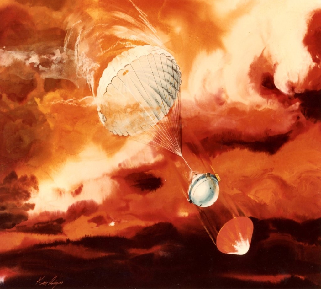
Figure 1 is an artist’s rendition of the Galileo Atmospheric Probe penetrating the Jovian atmosphere. The scene depicts the heat shield being ejected (lower right) and the parachute slowing down the deceleration module aeroshell (instrumentation section) prior to collecting data on Jupiter’s atmosphere.
Ensuring the precise choreographed sequence of events shown in this photograph formed the crucial test objectives for the Project Galileo test at WSMR. As one goal, the project needed to ensure that the parachute used for deceleration was fully opened before the heat shield was ejected.
Photo credit: WSMR Museum Archives (Public Affairs Collection), furnished by NASA AMES Research Center, Mountain View, CA 94035. Image by Ken Hodges.
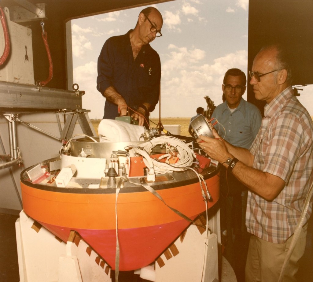
Figure 2 shows the Galileo Atmospheric Probe (GAP) undergoing preparations by NASA contractor personnel for the drop test conducted at White Sands Missile Range. The electronic and optical equipment installed inside the probe was designed to characterize the atmosphere of Jupiter; in addition to standard measurements such as temperature and pressure, atmospheric composition (atomic and molecular gases), electrical activity (i.e., lightning), cloud cover and other features of this exotic planet were also to be ascertained. The large orange conical section below the deceleration module aeroshell (instrumentation section) is the heat shield. The individual standing on the right is likely holding a communications module similar to the unit employed on the live mission.
One of the most important results derived from the GAP instrumentation during the live mission was that the atmospheres of Jupiter and the sun are composed of nearly the same proportion of hydrogen and helium. In this respect, it turns out that Jupiter is a “mini-me” of the sun.
Photo Credit: WSMR Museum Archives (Public Affairs Collection), US Army photo by Robert Baca & C. Montoya.
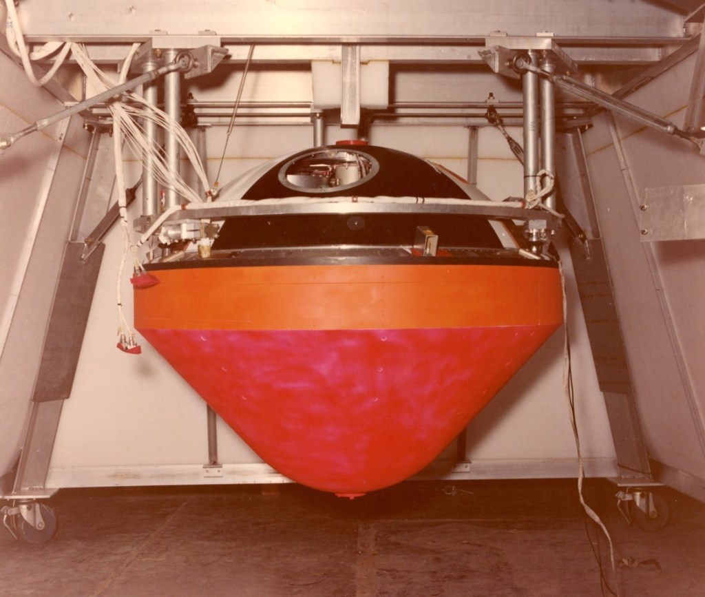
Figure 3 shows a detailed view of the Galileo Atmospheric Probe (GAP) mounted inside its protective shroud prior to being attached to the stratospheric balloon. The purpose of this shroud was to protect the probe from wind damage and other deleterious atmospheric effects prior to the drop event. The GAP at this time is fully assembled prior to liftoff, with the deceleration module aeroshell (instrumentation section) cover in place on top of the heat shield. The cylindrical device partially seen inside the port access window is likely the top of the mass spectrometer used to obtain precise measurements of the Jovian atmospheric constituents during the mission. The small red cylinder at the top of this module is the mortar tube cover for the enclosed descent parachute. The distance from the base of the heat shield to the top of the deceleration module aeroshell is three feet; the maximum diameter of the heat shield is slightly over four feet. The GAP was designed to withstand high levels of electromagnetic radiation as well as deceleration forces of several hundred G’s during entry into the Jovian atmosphere.
Photo Credit: WSMR Museum Archives (Public Affairs Collection), Air Force Geophysics Laboratory. Photo by Robert Baca & C. Montoya.
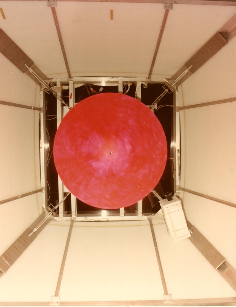
Figure 4 provides a unique view of the GAP inside the protective shroud, looking directly up at the heat shield; the shroud and GAP are completely assembled and ready for launch at this time. A television camera for collecting images at the time the GAP was released is seen on the right side of the shroud.
The heat shield for the GAP was designed to withstand an estimated 14,000°k during its entry into the Jovian atmosphere; the predicted time that extreme heating would occur during the mission was about two minutes. In order to achieve survivability, a phenolic resin ablative material was chosen for the heat shield. The concept was for the heat shield, as it entered the Jovian atmosphere, to ablate (literally cook off) some 60% of the phenolic resin before the GAP was slowed to Mach 1, at which point deployment of the decelerator (parachute) took place.
Photo Credit: WSMR Museum Archives (Public Affairs Collection), Air Force Geophysics Laboratory. Photo by Robert Baca & C. Montoya.
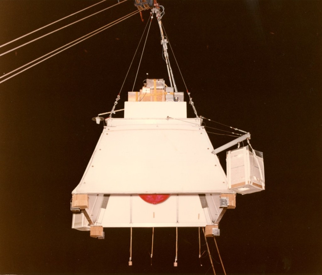
In Figure 5, the GAP is shown in its protective shroud, suspended from a launch crane, prior to being attached to the stratospheric balloon (the bottom edge of the heat shield is shown as the red circular object in the center of the shroud). The large container on the right of the shroud and similar container on the lower left edge are the ballast hoppers used to control the float altitude of the balloon and GAP prior to the drop. Additionally, the GAP carried 830 pounds of ballast in order to achieve a speed of Mach 1 during the drop exercise. The four lines extending down from the center-rear of the shroud are used to indicate the effects of any surface winds as the GAP was moved on the launch crane toward the balloon for launch. The boxes located on top of the shroud are the batteries and electronic controls; release of the GAP from the balloon over WSMR was initiated from an onboard programmed timer which was part of the electronics package. A radio beacon location device (not shown) was installed on the shroud to determine where it landed after completion of the drop test.
Photo Credit: WSMR Museum Archives (Public Affairs Collection), Air Force Geophysics Laboratory. Photo by Robert Baca & C. Montoya.

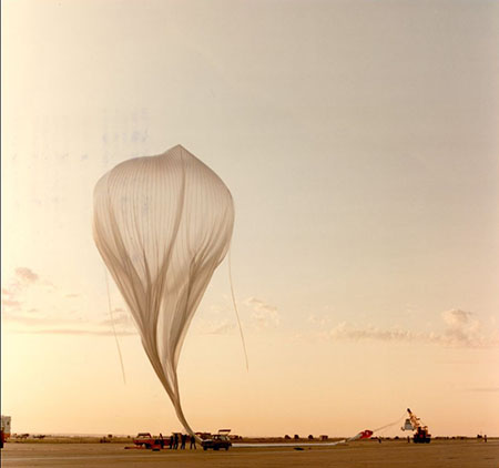
Figure 6 shows the stratospheric balloon, used to carry the GAP aloft, undergoing helium inflation at the Roswell Industrial Air Center in New Mexico. This single-stage, 5 million cubic foot balloon lifted the GAP to an altitude of 97,000 feet and traveled nearly 120 miles to carry out the drop test at WSMR. In this picture, personnel from the Air Force Geophysics Laboratory are shown inflating the balloon early on the morning of July 17, 1982. The yellow trailer in the center is the mainstay, used to gradually unroll the balloon material during the inflation process; in addition, the mainstay held the inflated balloon in place until its release at launch. At the left center of the picture, an individual can be seen unpacking the balloon from its factory wrapping prior to being fed into the mainstay rollers.
Photo Credit: WSMR Museum Archives (Public Affairs Collection), Air Force Geophysics Laboratory. Photo by Robert Baca & C. Montoya.

Figure 7 shows the shroud containing the GAP, suspended from the launch crane, moving toward the stratospheric balloon in preparation for launch (the so-called reeling-up operation). The balloon is seen in the background attached to the mainstay. The four lines at the bottom of the shroud are inclined away from the bottom edge, indicating that a ground wind is blowing in the direction that the launch crane is moving. The crane, operated by two individuals, will attempt to travel at the same speed as the wind in order to achieve a vertical alignment of the balloon and shroud at launch. The ballast hoppers are shown on the bottom diagonal corners of the shroud, along with the batteries and the electronics control containers on the top. The orange recovery parachute is being raised off the runway between the shroud and the balloon during the reeling-up operation. A vehicle used for helium filling is located to the left of the mainstay. At the top center of this figure, a small red weather balloon is seen ascending into the sky.
Photo Credit: WSMR Museum Archives (Public Affairs Collection), Air Force Geophysics Laboratory. Photo by Robert Baca & C. Montoya.

Figure 8 shows the payload ascending from the Roswell Industrial Air Center shortly after liftoff at 6:25am on July 17, 1982. This picture shows the protective shroud enclosing the GAP as it gains altitude for its nearly 120-mile flight west to WSMR, where the GAP will be dropped. The small dark circle in the upper center of the balloon is a valve used for venting helium in order to control the rate of ascent, as well as to assist in achieving a controlled descent after the drop has occurred. The two ballast hoppers are seen on the opposite sides of the shroud in this picture.
As the balloon begins ascending and traveling west from Roswell, WSMR radars and telemetry instrumentation will begin to record position and onboard functions in real time. As the balloon and GAP near WSMR, range optics will begin to record the drop event and GAP performance for subsequent analysis.
Photo Credit: WSMR Museum Archives (Public Affairs Collection), Air Force Geophysics Laboratory. Photo by Robert Baca & C. Montoya.

Figure 9 shows the impact of the GAP heat shield immediately south of the WSMR Space Harbor. The only apparent damage appears to be a detached part of the heat shield seen in the lower left of the picture. The heat shield appears to have penetrated only several inches into the sand.
Photo Credit: WSMR Museum Archives (Public Affairs Collection), Air Force Geophysics Laboratory. Photo by Robert Baca & C. Montoya.
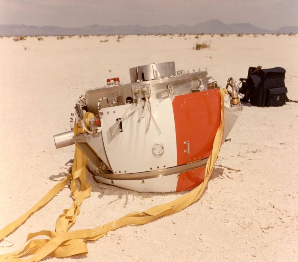
Figure 10 shows the impact of the deceleration module aeroshell (instrumentation section) south of the WSMR Space Harbor, not far from the heat shield shown in Figure 9. This module shows no apparent damage even after moderate penetration into the sand. Several of the yellow parachute suspension lines attached to the descent module are spread out on the desert floor.
Photo Credit: WSMR Museum Archives (Public Affairs Collection), Air Force Geophysics Laboratory. Photo by Robert Baca & C. Montoya.
Conclusion
What was the outcome of this test? Initially, the test was determined to be successful. However, after more careful post-test analysis of the data collected during the live event, it was determined that the heat shield was ejected before the deceleration module aeroshell’s parachute was deployed. This was the incorrect order of events, and NASA made engineering changes to correct this issue. This test was repeated a year later at WSMR and the results confirmed that the modifications made by NASA corrected the issue. The outcome of the test conducted at WSMR on July 17, 1982 possibly helped facilitate a successful outcome for the Galileo atmospheric probe’s historic flight into the Jovian atmosphere, some 23 years later, on December 7, 1995.