
The V-2 Rocket
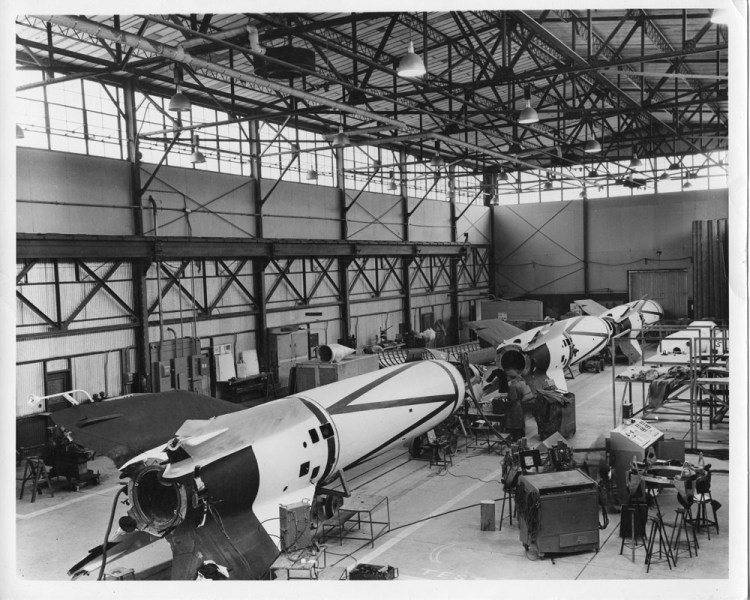
When the 300 carloads of missile components had been sorted and restored to usable condition, the rockets were assembled. The V-2 rocket consisted of five parts:
(1) Warhead
(2) Control compartment
(3) Midsection
(4) Thrust frame
(5) Tail assembly
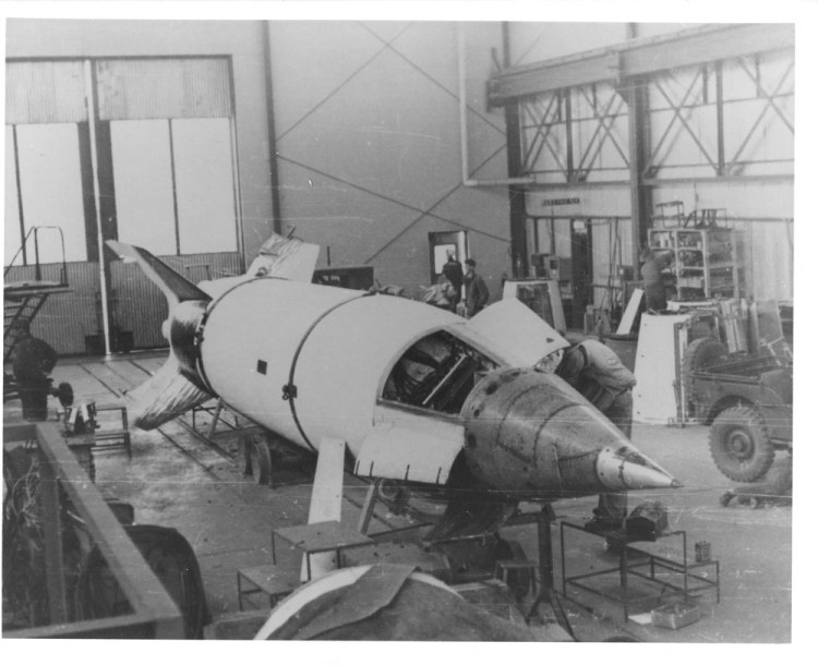
It used no booster. As assembled at White Sands Proving Ground, the overall length was 46 feet. Diameter of the body was 5 feet 5 inches, with a fin span of 11 feet 8 inches. Using a liquid propellant, the rocket unit developed a thrust of 52,000 pounds for 68 seconds. Launching weight was 28,413 pounds including 19,575 pounds of propellant. To accommodate experimental needs, major contour modifications were made on 24 missiles. Seventy-one percent of all missiles launched at White Sands Proving Ground were above designed weight and 11 missiles had modifications to the nose cone (warhead). By 1949, an addition of 47 percent had been made to the payload and by 1950, all V-2 rockets fired had major contour modifications.
A translated German manual on the A-4 (V-2) rocket.
Warhead
The German warhead proved too heavy for instrumentation and the instruments installed were inaccessible. Also, if the warhead were not fully loaded, the rocket would not be stable. During the war, this section of the V-2 had carried almost a ton of explosive; it was almost impossible to install enough instruments to equal such a weight. The Naval Research Laboratory designed special warheads, providing 20 cubic feet of space for instrumentation installation. These warheads varied due to the specialized space and design requirements of the experiment involved. Some of the instrumentation had to be pressurized, shielded or otherwise protected against the effects of flight. When it was not possible to install enough instruments to equal the 2,000 pounds necessary for stabilization of the rocket, lead weights were used to ballast the nose cone.
Control Section
This compartment was located directly below the nose cone and contained the gyroscopes that controlled the rocket in flight and the bottle of nitrogen gas which drove them. If the rocket deviated from a preset trajectory during flight, the gyroscopes produced electrical signals in the form of voltage proportional to the amount of correction necessary to rectify the error. These corrective signals were transmitted through an integrating computing element to the tail assembly where other mechanisms were set in operation so that the rocket resumed its preset and pre-computed course. Later, as space permitted, this compartment also contained Doppler, telemetering, and the emergency cut-off radio receiver.
The original German gyroscopes, in good condition, gave excellent performance. However, there were not enough recovered to equip all the V-2 rockets assembled at White Sands Proving Ground. Therefore, it was necessary to procure 140 additional copies of the German gyroscopes. With minor improvements, these performed just as well as those of German manufacture.
Midsection
The liquid propellant used in the V-2 consisted of alcohol and liquid oxygen. The tanks for these fuels and their associated valves and piping were housed in the center section. Glass wool was used to insulate the alcohol tanks and piping from the extreme cold of the liquid oxygen.
An adequate supply of these tanks had been recovered in generally good condition. Workmanship, particularly welding , was excellent and little to no repairs were needed. A few riveted connections required spot welding , but the majority of the tanks were in an excellent state of repair.
Thrust Frame
This section held the propulsion unit that generated the thrust which propelled the missile through space. The major components of the propulsion unit were:
(1) Turbopump
(2) Steam-generating plant
(3) Heat exchanger
(4) Combustion unit
(5) Pipelines
The turbopump was driven by steam generated by combining hydrogen peroxide and sodium permanganate. The tanks for these fuels were also located in this section.
Approximately 100 thrust frames and 200 each of the propulsion unit components were delivered to White Sands Proving Ground. They were in excellent condition and, except for the heat exchangers, required very little repair.

Tail Assembly
This assembly was designed to act as a fairing for the propulsion unit of the rocket, to stabilize flight, to steer the missile, and to carry the vanes and vane motors. It was constructed so that the missile could be supported in an upright position on the launching frame by the bearing surfaces of the fins. The major parts of this assembly were:
(1) Tail hull
(2) Four stabilizing fins with vanes
(3) Vane motors
(4) Antenna mounts with rod antennas
Three types of jet vanes were received at White Sands Proving Ground and were found to be in good condition. Many were rejected in test, but an ample number remained to adequately supply 100 missiles. Approximately 90 tail sections were recovered in usable condition, but considerable repair was required to make them serviceable. Toward the end of the V-2 program, it was necessary to have additional sections manufactured in the United States.
The function of the large fins was to stabilize to rocket in flight. At lower altitude, these fins functioned properly. However, at higher altitude, air density was not sufficient to maintain aerodynamic stability. At termination of thrust, the missile tumbled or dropped in a tail-down nose-up attitude. As the rocket re-entered denser atmosphere, the fins again became effective and the rocket regained a nose-down position. By painting various patterns on the fins and body, reference points were established and roll position data was more easily obtained.
An amazing history of the early years of today’s space program. Really a treasure trove of information and photographs! I was born in 1951 and in many ways grew up with the space program. The early years are fascinating. I’ve been reading “Rockets, Missiles and Space Travel” by Wiley Ley to gain an understanding of what it was like to be there as space exploration begin.
Three were successfully set up and launched over the Baltic Sea before the parts were divided for use by the British and American Armies.
This is new to mee following my documentation the British did fire over the North sea from Atenwalde a long the Danish coast.
Please see Operation Backfire volume 5
Thank you for your correction! The source document does say Baltic Sea, but I’m not sure why the author made the mistake. Thanks again!
Photo caption above: I am unaware of any captured materials were shipped from Amsterdam. The photo above was taken at the port of Antwerp
Thank you for the correction! That was an error on my part and I have fixed the mistake. Much appreciated!
Correction: the Backfire rockets were fired over the North Sea and not the Baltic.
Thank you for the correction! I looked at the source document and it does say the Baltic Sea, but that doesn’t make sense considering that Cuxhaven is on the North Sea, not the Baltic Sea. Unfortunately, the source document has no author, so I’m not sure how familiar they were with Operation Backfire itself or if this was just a typo. Thanks again!